
ASTM F1306
Puncture Test for Plastic Film
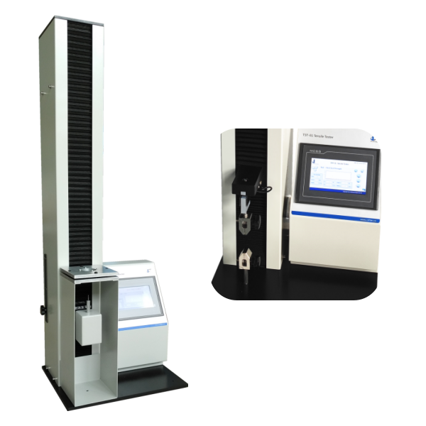
The ASTM F1306 test method is critical in evaluating the slow rate penetration resistance of flexible barrier films and laminates. For industries dealing with packaging, food, pharmaceuticals, and electronics, ensuring the durability and integrity of films against puncture is vital. This article provides a step-by-step guide on how to properly execute the puncture test for plastic film, based on ASTM F1306, using precise and reliable testing equipment such as the TST-01 Tensile Tester from Puncturetest.com.
ASTM F1306 Slow Rate Penetration Resistance Test for Plastic Film
ASTM F1306 is the Standard Test Method for Slow Rate Penetration Resistance of Flexible Barrier Films and Laminates. This method is designed to assess how a plastic film or laminate resists puncture when subjected to a controlled, slow rate of penetration using a hemispherical probe.
The importance of ASTM F1306 lies in its relevance to real-world applications where flexible packaging must withstand puncture from sharp objects. A breach in film integrity can compromise the product by allowing the ingress of gases, moisture, or contaminants, ultimately reducing shelf life and causing spoilage or failure.
ASTM F1306 - Plastic Film Puncture Testing Equipment Required
To conduct the slow rate penetration resistance test, the following apparatus is necessary:
- Universal Testing Machine with a calibrated load cell
- 3.2 mm hemispherical probe (standard for most applications)
- Film clamping fixture (secure and non-slipping)
- Specimen cutter for preparing 76 mm × 76 mm test samples
- Data acquisition software or chart recorder
The TST-01 Tensile Tester from Puncturetest.com fully complies with these requirements. It offers customizable clamping fixtures and advanced digital measurement software, ensuring accurate penetration depth, force, and energy readings.
Puncture Test for Plastic Film - ASTM F1306 Test Procedure
1. Conditioning the Sample
Before testing, condition all specimens at 23 ± 2°C and 50 ± 5% relative humidity for at least 40 hours, following ASTM D618.
2. Sample Preparation
Cut the film into 76 mm x 76 mm squares using a precise cutter. Ensure the film has uniform thickness, with no more than ±2% variation.
3. Equipment Setup
- Attach the hemispherical probe to the crosshead.
- Mount the clamping fixture and ensure proper alignment.
- Calibrate the tester and set the crosshead speed to 25 mm/min.
- Set the data acquisition resolution to 0.1 mm per data point.
4. Performing the Test
- Place the specimen in the clamping fixture.
- Lower the probe until it nearly touches the film surface.
- Start the test and observe until the probe punctures the film.
- Record peak force to break, probe penetration depth, and energy to break from the software.
5. Repeat and Average
Repeat the process on at least 10 specimens to obtain statistically significant results. Avoid eliminating outliers unless justified to avoid biasing the data.

Data Interpretation and Calculation
The test output typically includes:
- Peak Force (N): The maximum load before the film is punctured.
- Penetration Depth (mm): How far the probe traveled before breaking through.
- Work to Break (J): The energy absorbed by the film before failure.
Modern testers like the TST-01 calculate these values automatically. For analog systems, formulas are available in the ASTM F1306 standard for manual calculation.
Best Practices for Accurate Testing
- Avoid passive voice in reporting observations—clearly note when puncture or failure occurs.
- Keep the specimen clamped tightly to avoid slippage.
- Ensure probe alignment to prevent uneven stress distribution.
- Use consistent sample orientation, especially for multi-layer laminates.